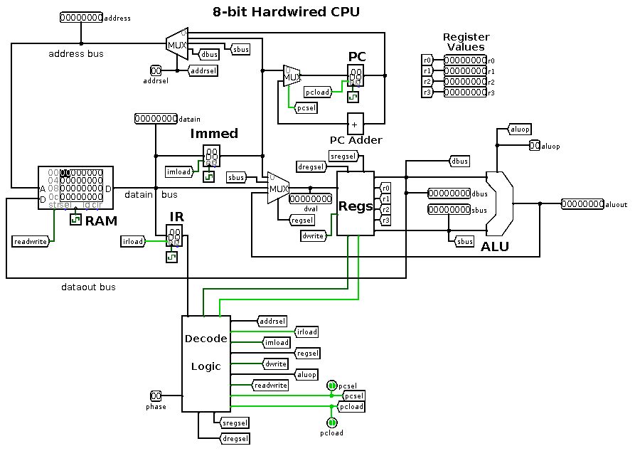
It normally executes logic and arithmetic op I highly recommend reading the following book if you would like to learn more about digital design: Become a member to follow this project and never miss any updates. It is also more than just a CPU in a simulator. The bit simple CPU in Logisim.
| Uploader: | Netilar |
| Date Added: | 27 October 2016 |
| File Size: | 30.30 Mb |
| Operating Systems: | Windows NT/2000/XP/2003/2003/7/8/10 MacOS 10/X |
| Downloads: | 12869 |
| Price: | Free* [*Free Regsitration Required] |
The only difference between this. Yes, delete it Cancel.
A 16-bit CPU in Logisim
The top left is the keyboard and top right is the TTY output, the big multiplexor allows crude channels for other devices, currently. The best answers are voted up and rise to the top. It only takes a oogisim to sign up. I did find a good reference on which canonical shift functions you should use in your VHDL code.

Specifically this demultiplexer would just be used to select which arithmetic operation to pick for an arithmetic instruction. We found and based on your interests.
D Flip-Flop is a fundamental component in digital logic pfocessor. Recycled the Python code from my previous custom CPU emulators and have it mostly working, although there are some bugs to fix. CoffeeTurtle Uncategorized April 26, April 26, Verilog code for t What is really great about VHDL is that it encourages i.
That will probably be a separate project.

When you are planning your micro-instructions you will need to clearly define in your own mind the "traffic" pattern for your data movement through your various blocks. I would highly recommend this to anybody starting out in VHDL.
Then at the 2 nd stage, we use a OR gate to OR all the outputs of 10 multiplexers. Warren Toomey's online notes etc: Improving the question-asking experience.
Subscribe to RSS
I can build a working accumulator it can't be accurately called an ALU, I think, because it lacks the L part that switches between addition and subtraction with a single input, and I understand this is all I need for the arithmetic part -- once I get jump opcodes working, I can implement multiplication and division in code. Thanks to the following: But I did follow Yann Guidon's advice of having 16 registers for a 16 bit machine and they can point to the whole 64K.
Here is a Picture of the Logisim design file that I created. The first one is to decode 3 bit RX to 8-bit control signal, the other one is to decode 3 bit RY to 8-bit control signal.
Besides, from the table, in each cycle we need a MUX 4 to 1 to select the control signal for 4 different instructions, so we use 3 MUX 4 to 1 for 3 cycles and each input of the 3 MUX 4 to 1 depends on the value of IR lohisim 8 th to 6 th. The screenshot of multiplexers.
A bit CPU in Logisim |
Description Based on an older scrapped project for an 8-bit computer, this is a bit CPU created in Logisim. And hopefully you'll have a lot of fun. Details in the figure 7 and 8. You are commenting using your Facebook account. I am still developing the emulator in Python and I will eventually create some kind of hardware, but these will be additional projects. Usually each bit of the accumulator is connected to each of the various function blocks via llgisim demultiplexer.
Clark Scott Warren Toomey's online notes etc: You are responsible for constructing the entire datapath and control from scratch. The screenshot of part 1 of 3 MUX 4 to 1.

No comments:
Post a Comment